Begin with one question
How a Rocket Reaches Orbit
Why is reaching orbit more about building sideways speed than only climbing upward?
Replay a two-stage ascent from liftoff through pitch, Max Q, staging, horizontal acceleration, and orbital insertion.
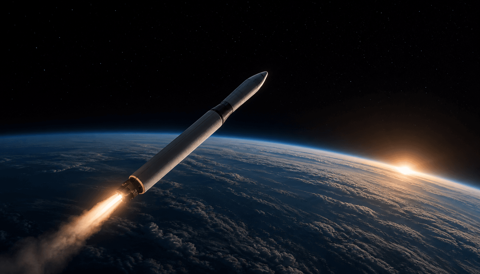
By the end of this lesson, you will be able to
Mission Control cannot call a launch successful from altitude alone. Engineers must connect every phase to the motion and trajectory it creates.
- 01Explain why an orbital launch begins vertically and then pitches downrange.
- 02Describe Max Q as a dynamic-pressure constraint rather than a destination.
- 03Connect staging to discarded mass and upper-stage performance.
- 04Judge orbital insertion using horizontal speed and projected perigee, not altitude alone.
- 05Read the major launch phases as an evidence chain inside Mission Control.
Space is above you; orbit is mostly across the horizon
Crossing an arbitrary altitude can place a vehicle in space without placing it in orbit. Orbit requires enough horizontal velocity for the falling vehicle to keep missing Earth's curved surface.
That is why an orbital launch does not continue straight upward. The trajectory must eventually become nearly horizontal while remaining above the atmosphere that would quickly remove orbital energy.
Climb first, then bend the velocity vector
At liftoff, thrust must first exceed the vehicle's weight. A nearly vertical climb clears the launch area and moves the vehicle through the densest air before large sideways motion develops.
Guidance then tilts the thrust vector. Gravity and steering curve the flight path downrange, so later engine impulse increasingly adds horizontal rather than vertical speed.
Max Q is where speed meets enough air to matter most
Dynamic pressure is q = ½ρv². Early in flight the air is dense but the vehicle is slow; later the vehicle is fast but the air is thin. Between them lies a maximum called Max Q.
Because aerodynamic loads scale with dynamic pressure, launch guidance and throttle plans must keep this region inside the vehicle's limits. Max Q is a constraint to pass safely, not a target to maximize.
Staging stops the upper stage from carrying empty machinery
As propellant burns, vehicle mass falls. When a lower stage can no longer contribute useful propellant, keeping its tanks and engines attached would force the remaining engines to accelerate dead mass.
Stage separation discards that mass. The lighter upper stage can then continue accelerating, usually while the trajectory becomes more horizontal.
Engine cutoff is where the trajectory must prove itself
After the final engine cutoff, the vehicle is no longer held up by thrust. It coasts in freefall, and its current position and velocity define the orbit.
A high altitude is insufficient if the projected perigee still enters Earth or dense atmosphere. A successful insertion needs enough horizontal speed for the lowest future point of the trajectory to remain safely above the atmospheric boundary.
Mission Control reads the ascent as one connected story
Altitude, vertical speed, horizontal speed, dynamic pressure, mass, staging events, and projected orbit answer different questions. No single number declares the entire vehicle healthy or the mission complete.
In Vastward's Launch-to-Orbit mission, the timeline tells you what should be happening while telemetry shows what the vehicle is reporting. Lesson 11 will add timestamps, quality, trends, and evidence handling to this physical story.
Build an Orbit, Not Just Altitude
Choose an ascent strategy, replay six flight phases, and decide whether the final altitude, sideways speed, and projected perigee produce an orbit.
Liftoff
First-stage thrust exceeds weight and the vehicle begins a nearly vertical climb away from the pad.
This profile diagram compresses altitude and distance. The path and vectors explain direction and evidence; they are not a real mission trajectory or a scale drawing.
- Mission elapsed time
- T+00:00
- Altitude
- 0 km
- Vertical speed
- 0 km/s
- Horizontal speed
- 0 km/s
- Dynamic pressure
- 0 kPa
- Vehicle mass
- 500 t
- Projected perigee
- -6,378 km
- Thrust from vertical
- 0°
The upper-stage engine has shut down at 205 km altitude. Which evidence best confirms orbital insertion?
Sources and evidence boundary
Vastward wrote this explanation independently and checked it against the official and research sources below. Each source supports a specific part of the evidence chain.
- Reviewed sourceChapter 3: Gravity and Mechanics — Newton's PrinciplesNASA ScienceOpen official source
- Reviewed sourceChapter 3: Gravity and Mechanics, How Orbits WorkNASA ScienceOpen official source
- Reviewed sourceFlight to OrbitNASA Glenn Research CenterOpen official source
- Reviewed sourceDynamic PressureNASA Glenn Research CenterOpen official source
- Reviewed sourceBasics of Space Flight: Chapter 14, LaunchNASA ScienceOpen official source